When the Linux Bridge Chokes at 2 AM
It was 2:14 AM on a Tuesday when PagerDuty fired. Our payment gateway—pumping roughly 120,000 packets per second across six Docker containers on a 10GbE link—was dropping roughly 8% of all inbound transactions. Host metrics looked grim: CPU cores 0 and 1 were pegged at 100%, saturated by ksoftirqd. Latency percentiles had exploded from a steady 1.8 ms to over 450 ms.
The host dmesg log immediately exposed the culprit:
# dmesg -T | tail -n 2
[Tue Oct 28 02:14:11 2025] nf_conntrack: table full, dropping packet
[Tue Oct 28 02:14:12 2025] nf_conntrack: table full, dropping packet

# top -b -n 1 | head -n 12
  PID USER      PR  NI    VIRT    RES    SHR S  %CPU  %MEM     TIME+ COMMAND
   14 root      20   0       0      0      0 R  98.7   0.0  12:43.11 ksoftirqd/0
   21 root      20   0       0      0      0 R  97.4   0.0  11:15.82 ksoftirqd/1
The standard Docker bridge (docker0) had collapsed under conntrack churn. In default bridge mode, every packet crosses veth pairs, traverses software bridge hooks, hits Netfilter NAT tables, and allocates a state table entry. Bump nf_conntrack_max from 65,536 to 262,144, and you only buy yourself an extra twenty minutes before RAM fills and softirq stalls return.
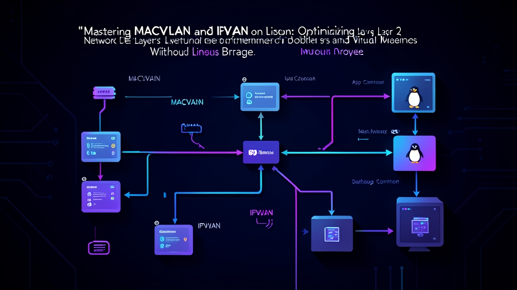
For standard CRUD APIs handling 2,000 requests per second, bridge overhead barely registers. But at line rate—with Kafka brokers, Redis clusters, or streaming ingest nodes—the bridge becomes a liability. The fix? Bypass virtual bridges and connection tracking entirely by attaching container namespaces directly to the physical NIC with MACVLAN or IPVLAN.
Architecture: MACVLAN vs. IPVLAN
Both drivers strip out intermediary hops, but they handle Layer 2 and Layer 3 headers in fundamentally different ways.
The Traditional Bridge Path
Standard Docker networking routes packets through a congested software pipeline:
Physical NIC (eth0) <--> iptables (NAT / MASQUERADE) <--> Linux Bridge (docker0) <--> veth peer <--> Container eth0Each frame incurs packet buffer copies, checksum verification steps, and CPU context switches between kernel namespaces. MACVLAN and IPVLAN eliminate this pipeline by plugging directly into the physical driver queue.
MACVLAN: Unique MACs on One Interface
MACVLAN assigns discrete virtual Layer 2 MAC addresses to sub-interfaces bound to a physical parent interface like eth0. Each container pulls an IP directly from your physical subnet:
Upstream Switch <--> Physical NIC (eth0)
                         |-- eth0.1 (MAC: 02:42:0a:00:00:02, IP: 192.168.10.10) -> Container A
                         |-- eth0.2 (MAC: 02:42:0a:00:00:03, IP: 192.168.10.11) -> Container B
Your top-of-rack switch sees one physical port housing several distinct MAC addresses. MACVLAN supports four operational modes:
- Bridge mode (Default): Containers on the same parent communicate locally in kernel memory. Frames never leave the host NIC.
- VEPA (Virtual Ethernet Port Aggregator): Intra-host container traffic is pushed out to the physical switch and hairpinned back. This lets you enforce access policies directly on hardware firewalls.
- Private mode: Drops all inter-container communication on the same parent, even if the upstream switch attempts to hairpin the packet.
- Passthru mode: Hands the entire physical interface exclusively to a single container namespace, bypassing virtual sub-interfaces.
The catch: MACVLAN requires physical switch ports that allow promiscuous mode or large CAM table allocations. Deploying MACVLAN on AWS VPC, Google Cloud Platform, or Microsoft Azure fails immediately. Cloud hypervisors drop any packet carrying an unauthorized MAC address.
IPVLAN: Single MAC, Multiple IP Addresses
IPVLAN bypasses the cloud MAC-filtering restriction. Rather than generating fresh Layer 2 addresses, every IPVLAN sub-interface clones the parent NIC’s MAC address (eth0). Only the Layer 3 IP address changes:
Upstream Switch <--> Physical NIC (eth0) [MAC: 52:54:00:ab:cd:ef]
                         |-- ipv0 (MAC: 52:54:00:ab:cd:ef, IP: 192.168.10.10) -> Container A
                         |-- ipv1 (MAC: 52:54:00:ab:cd:ef, IP: 192.168.10.11) -> Container B
Demultiplexing occurs at the network layer. The kernel inspects destination IPs inside incoming frames and routes them into the matching container. IPVLAN provides two primary modes:
- L2 Mode: Operates like a MACVLAN bridge, but preserves a single MAC. Broadcast and ARP queries still function, and your default physical gateway routes external traffic. It works smoothly in enterprise networks with 802.1X port security.
- L3 Mode: Turns the host into an internal router. ARP and broadcast domains disappear entirely. The Linux kernel switches incoming packets based purely on destination IP routing tables, delivering maximum throughput for dense microservices.
Step-by-Step Implementation
Switching drivers requires five minutes of setup and zero downtime on existing bridge networks.
1. Identify Network Parameters
Collect your parent interface name, subnet, and default gateway:
# ip -br addr show dev eth0
eth0             UP             192.168.10.50/24 fe80::5054:ff:fe12:3456/64

# ip route show default
default via 192.168.10.1 dev eth0 proto dhcp metric 100
Here, the parent interface is eth0, the gateway is 192.168.10.1, and the physical CIDR is 192.168.10.0/24.
2. Configure MACVLAN in Docker
Carve out an isolated IP range inside your physical subnet. Using --ip-range prevents Docker from assigning addresses already occupied by static servers or DHCP pools:
docker network create -d macvlan \
  --subnet=192.168.10.0/24 \
  --gateway=192.168.10.1 \
  --ip-range=192.168.10.192/27 \
  -o parent=eth0 \
  prod-macvlan-net
This isolates 32 addresses (192.168.10.192 to 192.168.10.223) strictly for container workloads. Start an instance:
docker run -d --name payment-processor \
  --net=prod-macvlan-net \
  --ip=192.168.10.195 \
  nginx:alpine
Confirm the container’s interface:
docker exec payment-processor ip addr show eth0The container holds a unique MAC address and the static IP 192.168.10.195. External hosts on the physical network can hit this IP directly—no -p 80:80 port publishing, no iptables NAT rules, and no conntrack entries.
3. Fix the Host-to-Container Communication Blackhole
Run a ping from the Docker host to 192.168.10.195. Packets drop 100% of the time. The Linux kernel blocks direct packet flow between a physical parent interface and its MACVLAN child endpoints to prevent broadcast loops.
To establish bidirectional traffic, configure a dedicated MACVLAN link on the host:
# 1. Add a virtual macvlan interface to the host
sudo ip link add macvlan-shim link eth0 type macvlan mode bridge

# 2. Assign a reserved host IP from the physical subnet
sudo ip addr add 192.168.10.220/32 dev macvlan-shim
sudo ip link set macvlan-shim up

# 3. Route container traffic through the shim
sudo ip route add 192.168.10.192/27 dev macvlan-shim
Verify connectivity from the host:
# ping -c 3 192.168.10.195
PING 192.168.10.195 (192.168.10.195) 56(84) bytes of data.
64 bytes from 192.168.10.195: icmp_seq=1 ttl=64 time=0.048 ms
64 bytes from 192.168.10.195: icmp_seq=2 ttl=64 time=0.039 ms
64 bytes from 192.168.10.195: icmp_seq=3 ttl=64 time=0.041 ms
Latency drops from 1.8 ms to 41 microseconds. Host-to-container calls now route smoothly through the shim.
4. Deploy IPVLAN L2 Mode
For cloud VMs or switches enforcing port security (sticky MAC), use IPVLAN L2:
docker network create -d ipvlan \
  --subnet=192.168.10.0/24 \
  --gateway=192.168.10.1 \
  --ip-range=192.168.10.224/27 \
  -o parent=eth0 \
  -o ipvlan_mode=l2 \
  prod-ipvlan-l2
Launch a container on the new network:
docker run -d --name metrics-collector \
  --net=prod-ipvlan-l2 \
  --ip=192.168.10.225 \
  alpine sleep 3600
Compare hardware addresses between host and guest:
# Host physical MAC
cat /sys/class/net/eth0/address

# Container MAC
docker exec metrics-collector cat /sys/class/net/eth0/address
Both return identical MAC strings (e.g., 52:54:00:12:34:56). The physical switch observes one hardware address, yet forwards traffic to distinct IPs without filtering drops.
Driver Selection Rules
Avoid tuning conntrack tables when your workload outgrows bridge capacity. Instead, choose the driver built for your physical infrastructure:
- Use MACVLAN on bare-metal servers or private VMware/Proxmox clusters where the network team permits multiple MACs per switch port, and services require raw Layer 2 broadcast discovery.
- Use IPVLAN L2 on public clouds (AWS EC2, GCP Compute Engine), wireless interfaces, or corporate networks with rigid MAC port security policies.
- Use IPVLAN L3 for high-density backend microservices where you can peer BGP routes with upstream routers to eliminate broadcast noise and ARP table overhead.
Always document host shims in your configuration management playbooks, partition your CIDRs deliberately, and monitor drops via ip -s link show eth0.